

This Bushranger product comes specifically designed to meet the requirements of the specified applications. Thus, being engineered to a high standard, the Bushranger winches provide safe and dependable service following the manufacturer’s instructions. Proper care and preventative maintenance will provide years of trouble-free operation.
A careless winch operation can result in severe injury or property damage to the operator and others around him. Unless otherwise stated, this article outlines the most recent product information available for Bushranger Winches.
To ensure your safety, please take the time to read and comprehend this document before installing and operating the winch.
 Preparation of the Rope
Achieving a tight and uniform wrap around the drum when using the rope for the first time must be tensioned onto the drum under load before use. It is possible to permanently damage a cord if it is not tensioned and wound tightly and evenly before use. This is because the outer layers of the cable can draw down into the inner layers of the string, resulting in binding, pinching, or wedging between the layers.
If the vehicle is parked on a slight incline, one method for securing the rope to the drum is to pull on the rope as it is spooling into the drum with the vehicle’s weight. Before spooling in under this load, make sure the cord is pulled out to the point where there is only the bare minimum of wraps. Using the steps outlined in the following section, “Winching Procedures,” you will be able to accomplish this (Page 14).
Installation
We strongly recommend that a qualified technician familiar with the product carry out the installation. The winch is supplied with a variety of bolts to accommodate the various mounting options, including:
- A note on bolts: Ensure that the winch mounting can withstand the loads applied. Thus, installation must include the use of four high tensile steel bolts (supplied).
Permanently mount on a flat and hard surface or in a suitable winch-compatible mounting channel. Or in a convenient winch-compatible bull bar to ensure that the motor, drum, and gearbox housing align with the rest of the vehicle.
- Due to the design of the fairlead is not intended to be mounted directly to the winch.
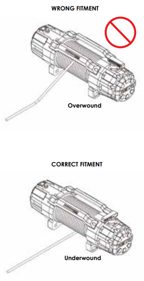
- The rope must be wound in an under-wound orientation only.

Installation of the control box
The Control Box’s design has included several mounting options to accommodate various installation locations and orientations. A stick on the label (Bushranger) comes as a loose item in your winch kit. Apply to the Control Box once the installer has determined a suitable mounting method and correct direction.
Recommendations for Batteries
Your Bushranger winch’s proper operation depends on the fully charged battery and adequately connected connections. Cold-cranking amps of 650 are required for a 12 Volt DC battery to meet the minimum requirements.
Routing of Cables
The control box is delivered with the power cables exiting through the centre opening on the underside face of the box’s front panel. The wires can also be routed to leave the control box through the sides, which may be more suitable for specific installations than routeing them through the centre.
Remove the plastic control box cover and, using a sharp knife or cutters, cut out either the left or right-hand side of the control box, as shown, to reroute the cables through the sides. Removal of the black contactor unit delivers the wires through the new opening created at the top of the inclosure.
Option 1 for mounting: Bracket for mounting.
A steel mounting bracket is provided for applications in which the Control Box is installed independently of the winch. Thus, clearance underneath is required for the Control Box. Remove the plastic control box cover by loosening two screws on each side of the control box. Then align the steel mounting bracket with the four holes in the control box’s base plate and tighten the screws.
Bolts (not included) to secure the mounting bracket to the mounting surface. Use four M5 bolts to secure the bracket to the base, and then replace the plastic control box cover on top of the frame. The bolts should be threaded through the slots in the mounting bracket – they should be used.
Directly to the winch – Option 2 of mounting
The Control Box can be mounted to the winch’s crossbars for convenience. Remove the plastic control box cover and align the four x holes in the base plate with the four x threaded holes in the winch tie bars by removing the plastic control box cover.
Secure the control box to the winch with four M5 bolts, and then replace the plastic control box cover with a new one.
Vertical mounting is the third mounting option.
Additionally, the Control Box can be mounted vertically to a surface. Remove the plastic control box cover and align the slots in the base plate with the holes in the flat surface to which the control box will be mounted. Replace the plastic control box cover. Apply two or more bolts (not included) to secure the control box to its mounting surface before reinstalling its body made of polycarbonate plastic.
 Rotation of the gearbox
The gearbox end can be rotated in 22.5° increments to allow the clutch handle to be oriented most conveniently for the installation requirements.
Important Note:
- Loosen and partially remove the eight x bolts connecting the two gearbox sections to the winch. The gearbox sections should not be removed from the winch.
- As shown in the diagram, rotate both gearbox sections and bolts simultaneously to achieve the desired angle. Check to see that the gearbox seal reseats in the proper position.
- Replace all bolts and tighten them all to 6Nm with a torque wrench. The use of power tools, such as an impact driver, is not recommended. Stripping of bolt threads and the head of the socket head bolt are possible consequences of this.
Rotation of the motor
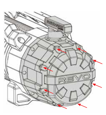
The motor can be rotated through three positions in 90-degree increments. It allows the poles to be repositioned to best suit the installation requirements in each situation. These are the positions of 0°, 90°, and 270°. Tighten and remove the six x bolts that hold the motor cover in place on the drum support assembly. Remove the motor cover from the winch and set it aside.
Remove the two x bolts that hold the motor to the drum support by loosening and partially removing them. Rotate the engine into position, ensuring that the motor seal reseats into the proper place.
Reinstall the motor bolts and tighten them to a torque of 10Nm. Reinstall the motor cover and tighten the six bolts to 1.5Nm with a torque wrench to complete the installation process. The use of power tools, such as an impact driver, is not recommended. Stripping of bolt threads and the head of the socket head bolt are possible consequences of this.
Schematic representation of the wiring diagram
Install both leads securely to the negative (–) battery terminal and the positive (+) battery terminal, as shown below. Install the winch as close to the battery to get the best performance. For the winch motor to operate correctly, the voltage drop must not be more significant than 10% of the nominal 12V.
On the REVO 10S and 12S models, a 2m long red power wire with an inline fuse exits the control box. Therefore, it should be connected to a switched power source to wire the wireless receiver. We recommend that you join the wireless device to the vehicle”s ignition or accessories circuits. Furthermore, which will allow you to use it only when your 4×4 is turned on. Another option is to route it through a dash-mounted on/off switch, allowing the user to turn on and off the wireless function as needed.
The Nut Fastening System for the Motor and Contactor
Using the diagram below, tighten the nuts on the motor and contactor to the specified torque. It is possible that damaging the studs will result from attempting to pull the top nut without first locking the bottom nut. Do not tighten the top nut until the bottom nut has been closed.
Principles of Winching
Note: It is recommended that users of this recovery equipment receive formal training in winch operation and vehicle recovery from an accredited industry body before using the equipment.
Using the Fleet Angle Calculator
Duty for Load Rating Ratings for Cycles:
The direction of pull should be on a horizontal plane within 15 degrees of the winch drum’s centerline and perpendicular to the winch drum. But within 15 degrees of the winch drum’s centerline, obtain the best rope service. It is possible to have incorrect spooling if the fleet angle is greater than the recommended angles. Thus, the rope loading onto one side of the rope drum and potential damage to the cord or winch.

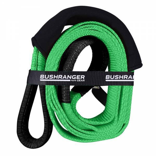
Recovery Gloves (Included)
Load Capacity
The rope amount on the drum affects the load and speed of the drum. The first layer of rope on the drum is responsible for the slowest pace and the most significant amount of weight. A fully loaded drum delivers the highest possible rate while carrying the most negligible possible load. As a result, the capacities of automotive winches are specified in terms of first layer capacities.
Required Pull Force
You must have enough power in your winch to overcome the resistance created by an obstacle. According to general guidelines, you’ll need a winch with a maximum line pull that’s at least 1.5 times the gross vehicle weight, if not more.
Three factors impact the line pull effect required to recover the vehicle from the ditch. The values and calculations are approximate and are provided solely for illustration.
GVM (gross vehicle mass) (type of surface to be traversed) (gradient to be overcome) are all factors to consider.
In recovery and loading situations where the winch is used to pull something, the required pulling force (RPF) can be calculated using the following formula: Recovery and loading.
RPF is equal to (Wt X S) + (Wt X G)
The following formula would be applied in the following scenario: A vehicle weighing 3,000kg is winched up at an incline of 100 per cent on a marshy surface.
Note: A gradient of 10% corresponds to a rise of one metre in ten metres (Height/Distance) when the distance is one metre.
Where RPF Wt is 3,000kg, the effect required to recover the vehicle is calculated as (Wt X S) + (Wt X G)
S: 0.52 G: 0.71 S: 0.52 G: 0.71
In this equation, Wt S G = the gross vehicle mass (GVM); the type of surface to be traversed; the gradient to be overcome.
 The new Wireless Hand Controller can be paired up.
Suppose you need to replace a hand controller unit or have lost your pairing. In that case, you can pair a new controller to the wireless receiver by following the steps outlined below. The previous pairing of the wireless receiver with a hand controller must first be cleared from the receiver’s memory for the current pairing to take effect.
It is important to note that the wireless receiver is located in the control box and is usually wired into the vehicle’s ignition system. To turn the wireless receiver ON or OFF, turn the key or flick the button on the remote control. Or to a separate switch.
Preparation Before the Winching Operation
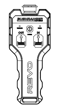
Step 1: Connect the remote control to the computer.
Ensure that the remote control lead is correctly aligned by connecting each end to the corresponding plugs on the remote control and control box, as shown in the diagram. Collars should be tightened to ensure reliable connections. To activate the wireless controller, press and hold the Power Button for three seconds to turn it on and off. When the remote control is not in use, disconnect it.
Step 2: Release the clutch.
Turn the clutch handle counter-clockwise until it is in the “Disengaged” position (see illustration). The rope is now free to be unwound from the drum by hand, which is what you want to do. It is never safe to release the clutch when the string is under load. Do not disengage the clutch if you are powering out in Step 3.
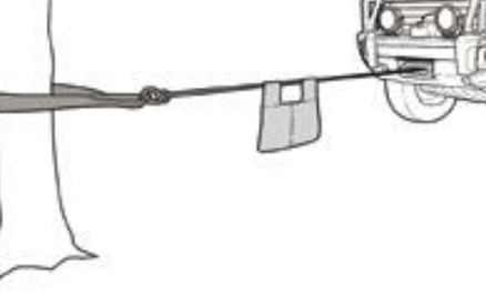
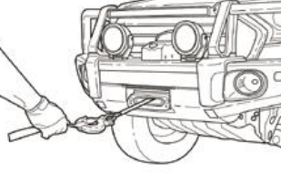 Step 3: Pull or power out the rope to the anchor point in the third step.
Holding the Pull Strap, pull or power out enough rope to reach the anchor point until the Strap snaps. When unwinding the cord, keep the tension on it. When working with rope, make sure to use the proper gloves.
Step 4: Make use of the clutch.
When you want to engage, turn the clutch handle in a counter-clockwise direction until it says “Engaged.” The clutch should never be engaged while the drum is rotating. Turning the drum slightly by hand may be necessary to ensure proper engagement.
 Step 5: Start winching as soon as possible.
Maintain tension on the rope to ensure that it winds onto the drum tightly and evenly and does not sink into the lower layers. Release the hand brake and continue to pull until the vehicle is located and towed away.
Step 6: Make sure your vehicle is secure.
Once the vehicle is securely fastened, wind the remaining rope around the drum tightly and evenly, and tighten the hook to ensure it is secure.
Disconnect the remote control from the Bushranger winch.
Each end of the remote control lead should be disconnected from the remote and the control box. To deactivate a wireless controller, press and hold the Power Button for three seconds to turn it off completely. The remote control storage should be safe, dry, and easily accessible.
Maintenance:
lubrication and maintenance
A licenced and certified technician should perform servicing and repairs. In unauthorised maintenance or servicing, the warranty will be voided. The maintenance schedule should be adhered to to ensure that the winch operates reliably for its service life. The winch should be used regularly to ensure that all components remain in good working condition. The rope should be powered out and then powered back in monthly, at the very least. This should be accomplished by following the proper winching procedures.
The drum support seals are a worn item that must be replaced regularly to keep the winch’s sealed design in good working order. Analysing how frequently they are used and the operational environment, they should be inspected, greased, or replaced. Most moving parts in the Bushranger winch are permanently lubricated with synthetic oil at assembly. Factory lubrication will suffice under normal operating conditions to keep things running smoothly. Shell EP2 or an equivalent grease should be used if re-lubrication of the gearbox is required following a repair or disassembly. Light oil lubricates the clutch handle regularly.
Cleaning:
Only use low-pressure water at a low pressure to clean the synthetic rope. Do not use any chemicals in your home. If you want to clean the winch, we recommend using low-pressure water and a soapy sponge.
It is not recommended to direct high-pressure water at the drum area or the clutch handle when cleaning the clutch. Using high-pressure water in these areas can force water past seals, resulting in internal water buildup that can cause damage to the winch’s bearings.
Warnings:
- It is highly recommended that users receive off-road vehicle recovery training before using this off-road vehicle recovery winch. This training should include vehicle recovery. This winch should only be used with extreme caution when recovering immobilised vehicles, as it is potentially dangerous.
- The winch is rated for intermittent periodic duty when the first layer of rope on the drum is pulled tight.
- For safety, the winch is not to be used to lift, support, or transport personnel other than as described above.
- According to the manufacturer, the rated load must be supported by at least five wraps of steel wire rope and ten (10) wraps of synthetic rope wrapped around the drum.
- While operating, keep body parts and loose clothing away from the winch, rope, hook, and fair lead.
- The rope can snap at any time without warning. When working with a winch and rope, always maintain a safe distance between yourself and the equipment.
- The winch is not correctly aligned, supported, or attached to a suitable mounting base. It may reduce performance efficiency or even be damaged along with the rope and mounting platform.